Printing Thin Walls and Small Features
If you have ever tried printing very small or thin features on your 3D printer, you’ve probably noticed that this can be a challenge! Most 3D printers have a fixed nozzle size, so if you want to print something that is only 50% as wide as your nozzle (or 150% for that matter) this requires some special attention. Thankfully, Simplify3D includes a whole set of features that have been created for this exact scenario. This tutorial will help you understand the thin wall settings that exist in Simplify3D and how you can use those settings to improve your 3D prints!
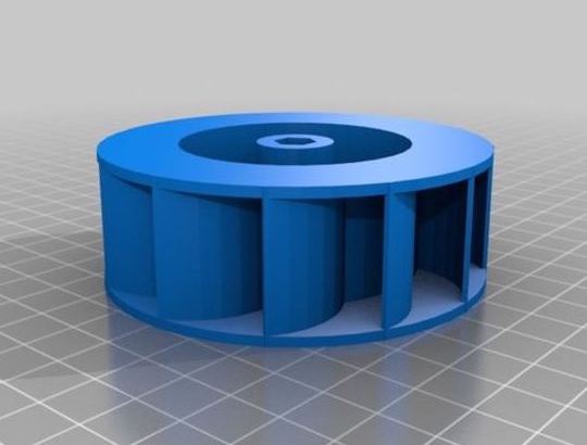 First of all, it’s important to understand that even large models can have difficulty with small features. For example, a large part may still contain thin walls within the model itself. Many parts also contain sharp or tapering edges that could produce very thin extrusions. So regardless of what type of models you are printing, it can be useful to learn about these special features. For this tutorial, we are going to use the “Toy Open Water Turbine” model by user Non-ICE. This model contains several thin, tapering blades that connect to a narrow hub in the center of the model. We have set up a factory file that contains this model along with the initial settings for this tutorial. Click here to download the factory file so that you can follow along.
For the purpose of this article, we are going to separate these thin features into 2 categories – external and internal. External thin walls are very thin features that are visible from the outside of the model. For example, if your nozzle was 0.4mm wide and you were printing a wall that was only 0.2mm thick, this would be an external thin wall. Internal thin walls are small voids or gaps that may appear on the inside of your model. If you were printing a 1.0mm wide wall with a 0.4mm nozzle, there may be a small internal gap between the perimeters on either side of the wall. We will look at each of these wall types separately so that you understand how to configure Simplify3D for each scenario.
External Thin Features
Download the factory file that we provided for the Turbine Wheel and open this file in Simplify3D. The model contains several very narrow blades that are only about 0.35mm thick. If you click “Edit Process Settings”, you can see that the default settings that were included in the factory file use a nozzle diameter of 0.4mm. This means that the blades of our turbine wheel are actually smaller than the nozzle that we are printing them with! Because of this, if you click “Prepare to Print” in Simplify3D, you will notice that the blades are missing from the preview. By default Simplify3D will not print features that are smaller than your extrusion width, however, the software gives you full control to customize this behavior.
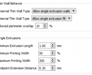
If you click “Edit Process Settings” and then navigate to the Advanced tab, you will see an entire section dedicated to thin wall behavior. By default, the “External Thin Wall Type” is set to “Perimeters only”. This means that the software will try to print the exterior walls of your model using only perimeters. This is a great default setting for regular sized prints where you want to maintain structural integrity in the part. However, for very thin features like our turbine blades, we want to change this option to “Allow single extrusion walls”. This tells the software that if it encounters a thin wall that cannot be printed with normal perimeters, it can try to print that wall by creating a separate extrusion for the thin shape. Click OK to save this change, and then click “Prepare to Print” to view the changes in the preview.


Left: Perimeters only, Right: Single extrusion walls (blades seen in dark blue)
As you can see, the blades of the turbine wheel are now included in the preview. If you change the previewing coloring mode to “Feature Type”, you will see that the fan blades are shown in dark blue, indicating that they were printed using external single extrusions. The software will automatically adjust the amount of plastic that is extruded in these areas to try to match the desired shape as closely as possible. Simplify3D also has the ability to vary the thickness of these extrusions, allowing you to print shapes with a varying cross section. For example, if the blades of this model had tapered from 0.35 to 0.25mm, the software would have made the appropriate adjustments to achieve the tapering effect. So you can quickly see how useful single extrusions can be if you are printing small external features!
Internal Thin Features
Now, we are going to use the same turbine model to explore internal thin features. Zoom in to the top of the model and you will find a central hub with 4 spokes that connect to the rim. These spokes are about 1.4mm wide, so when printed with a 0.4mm extrusion width, you will have one 0.4mm perimeter along each side of the spoke with a 0.6mm wide gap between those perimeters. If you analyze these spokes in the Simplify3D preview, you will see that the software uses something called “gap fill” to fill in the space between the perimeters. Gap fill is similar to the normal infill on the interior of your model. The extruder moves in a back-and-forth pattern, extruding lines of plastic that connect both perimeters together. This can be useful since it creates many structural connections between these perimeters, however, there is another option that can fill those gaps in a single movement.
If you click “Edit Process Settings” and return to the Advanced tab, you will see that the “Internal Thin Wall Type” is set to “Allow gap fill” by default. An alternate way to fill these gaps is to use single extrusions, similar to the ones we just used for the external turbine blades. Choose “Allow single extrusion fill” to enable this option. When you click “Prepare to Print”, you will see that the gap between these spokes is now filled with a single extrusion that has been adjusted to fill the 0.6mm gap.


Left: Gap fill, Right: Single extrusion fill (seen in dark green)
If you set the preview coloring mode to “Feature Type” you will notice that the internal single extrusions are denoted with a dark green color. As before, the software will adjust the amount of material that is extruded to perfectly fill the internal gaps and voids in the model. Using single extrusions allows the printer to fill these gaps in a single pass instead of a back-and-forth pattern. This can improve your printing time and even produce a better surface finish as a result! If you look at the central hub in the very middle of the model, you will see the dark green single extrusions in this area as well. These single extrusions were printed in a single continuous loop, however, the thickness of the extrusions was dynamically adjusted along the loop to fill the varying gap between the perimeters. This is incredibly useful, allowing you to print more complex shapes knowing that the software will make the appropriate adjustments to ensure the best print quality.
Single Extrusion Settings
Now that you have seen how single extrusions can be used with your models, it’s time to learn about a few additional settings that adjust how these single extrusions are printed. All of the settings below are found on the Advanced tab of your process settings. These settings apply to both internal and external single extrusions.
-
 Allowed perimeter overlap – This setting determines the preference between perimeters and single extrusions. If the walls become narrow enough that the perimeters overlap by more than this amount, single extrusions will be used instead. Use higher values if you want to create more perimeters, or smaller values if you want to create more single extrusions.
 -
Minimum Extrusion Length – If a single extrusion is shorter than this distance, it will not be printed.
This is useful, as it allows you to filter out very small movements saving valuable print time. - Minimum and Maximum Printing Width – You may find that your printer has trouble printing extremely small or very thick extrusions. These settings allow you to limit the width that the single extrusions will be printed with. For example, if you were using a 0.4mm nozzle with a 50% minimum extrusion width, this means that all single extrusions that are printed will be at least 0.2mm wide. The same principle applies for maximum printing width.
- Endpoint Extension Distances – When printing single extrusions, it is important to ensure that the start-points and end-points of these extrusions are securely connected to the base model. For example, the inner end of our turbine blades may have difficulty sticking to the rim, as the toolpaths only have single point of contact. This setting gives the ability to extend the length of the single extrusion by the set value on both sides, which can increase the overlap with the base model to create a stronger connection.
As you can see, these settings add a lot of flexibility to customize how the single extrusions are printed. Make sure to adjust these settings appropriately to achieve the best results for your specific models.
Looking For More Articles to Improve Your 3D Prints?
Now that you have mastered printing thin walls and small features, be sure to check out all of the other articles that we provide to help you improve your 3D prints. Click the link below to view our complete article library with many more tips and tutorials!