Identifying and Repairing Common Mesh Errors
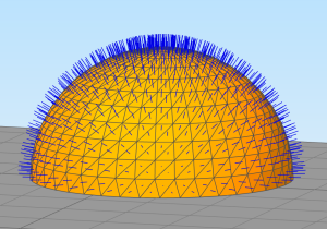 This tutorial will teach you about common mesh errors that you may encounter with your 3D printer. Digital models on your computer are typically represented by a large list of triangles. These triangles fit together to define the overall shape of your geometry and they are the basis for most 3D model formats like STL, OBJ, or 3MF. After you import a model into Simplify3D, you can go to View > Display Wireframe to show the millions of triangles that fit together to define your model. Each triangle is represented by 3 edges along with a normal vector from the center of the triangle that defines which side of the triangle is outward facing. If you go to View > Display Normal Vectors, the software will render a visual representation of the normal vectors using blue lines.
While this sounds simple enough, there are several common mesh errors you may encounter with real-world models. This tutorial will cover thin features, self-intersecting surfaces, missing triangles that create holes, backwards triangles, and even duplicate surfaces. But first, let’s talk about the warning signs that your mesh has problems.
Warning Signs for Problematic Meshes
When you import a 3D model into Simplify3D, there are several warning signs that could indicate a problem with the mesh. The first warning sign is visual discrepancies when the mesh is rendered on screen. You may notice holes in the surface of the mesh where you can see inside the part, or entire surfaces that appear to be transparent or discolored. This indicates holes in the mesh or triangles that are oriented in the wrong direction.
If you enable the normal vector display within Simplify3D (View > Display Normal Vectors), you can inspect the direction of the blue lines to determine if a triangle surface is oriented in the correct direction. For correctly meshed models, the blue lines should point outward from the surface of the part, responding hair or fur. If the mesh has an invalid orientation, the blue lines will point inside the part.
A final way to identify mesh errors is by slicing your part and reviewing the 3D preview that is generated for the print. Click Prepare to Print in Simplify3D to begin slicing and then use the Max slider at the bottom of the screen to change the number of layers that are displayed. As you move the slider from left to right you can check each layer for potential issues. If the visual preview looks different than the model you expected to create, there might be problems with the mesh. For example, you might notice entire regions being filled which should be hollow, or missing regions that were intended to be printed. These are all indicators of potential mesh issues.
Identify the Source of the Problem
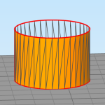 Once you suspect there is a problem with the mesh, there are several tools in Simplify3D to help identify the cause of the problem. The first tool can be found by going to Repair > Identify Non-Manifold Edges. This tool will verify that each triangle has 1 valid neighbor on each side. If a triangle edge does not have a valid neighbor, that edge will be highlighted in red to indicate a problem. If you see red lines on your model, this typically indicates gaps or holes in the mesh. A common example of this problem would be a cylinder that is missing an endcap leading a a ring of non-manifold edges. It may be easier to see these red lines by disabling the View > Display Shaded Surface option to hide the interior of each triangle. You can clear the results at any time by going to Repair > Clear Results.
 The next useful tool can be found by going to Repair > Identify Self-Intersections. This will look for triangles that incorrectly intersect with one another and are not properly stitched together. In the example on the left, a 3D modeling program was used to create a cube with a sphere on top, but the sphere was not properly joined with the cube. This leads to triangles that incorrectly pass through one another where the problematic areas are highlighted in red. You can use the View > Display Wireframe option to see the actual triangles that make up your mesh to verify the incorrect stitching.
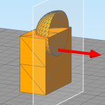 The final tool to mention is the Simplify3D Cross Section View. This tool will slice through your model, showing you the interior of the mesh. This can be helpful to view interior surfaces that may be causing some of the self-intersection or non-manifold problems. You can activate this tool by clicking the Cross Section icon on the right side of the Simplify3D interface or by going to View > Cross Section Settings. Use the displayed dialog to turn the cross section on of off, change the slice orientation or position, or change the displayed visualization in the 3D view. With the cross section gizmo enabled, you can drag the red arrow in the 3D view to interactively reposition the plane. In the example on the left, it is clear that the sphere passes through the cube instead of stopping at the intersection and only tracing the outer-most boundary.
How to Repair Mesh Errors
 Once you suspect there is a problem with your mesh, there are several convenient options to repair these issues in Simplify3D. The first and easiest method is to allow Simplify3D to repair the mesh automatically during slicing. This can frequently allow correct build files to be created for your 3D print without needing to manually fix the 3D model or CAD file in advance. To access these options, go to Edit Process Settings > Advanced tab, and review the Slicing Behavior settings in the bottom right.
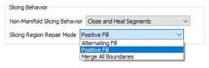
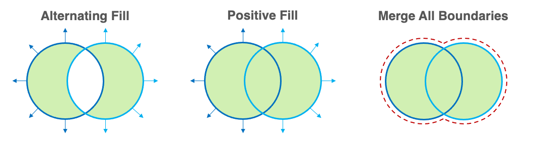
The first option we recommend trying is the Slicing Region Repair Mode. This is a very powerful setting that has several options.
- Alternating Fill – Imagine a line that is drawn directly through your 3D model. Each time this line hits one of the triangle surfaces, the software will switch between solid or empty fill.
- Positive Fill – All regions enclosed by outward facing triangles will be treated as a solid, and the software will attempt to automatically combine regions to heal self-intersection issues. This is the best choice for most models and is the default selection in Simplify3D.
- Merge All Boundaries – This extends upon the option above by ignoring the orientation of your triangles and assuming all regions inside of any triangles should be treated as solid. This is helpful for models that may have many incorrectly oriented surfaces, but the outer boundary is still in the correct position.
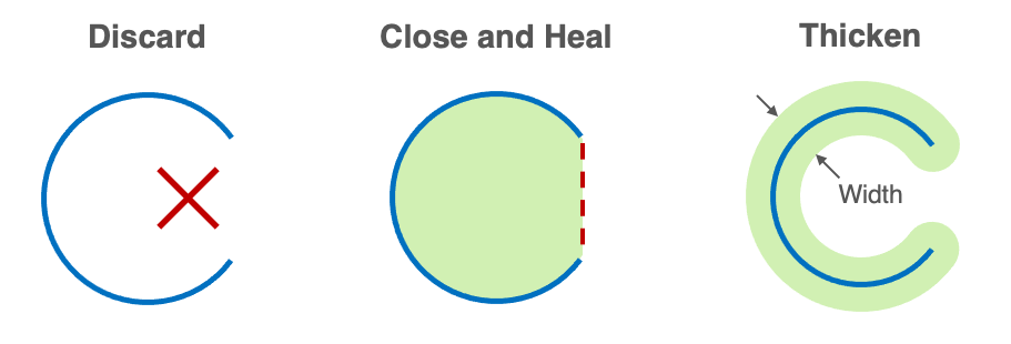
Another option in this same section that can be useful is the Non-Manifold Slicing Behavior. This settings determines how the software will treat outlines that don’t form a fully enclosed loop. These types of issues are common when the mesh has holes, cracks, or surfaces with no defined thickness. The software offers several choices to define how these open loops will be treated.
- Discard Invalid Segments – Any outlines that do not create a perfectly enclosed loop will be completely discarded. This can be a good choice if most of your model is correct, but you just want to discard a few pieces of invalid geometry that are causing issues.
- Close and Heal Segments – Open loops will be automatically closed off to create a valid printable region. This is the default selection and works quite well for most parts with small holes or cracks.
- Thicken Invalid Segments – Outlines that do not form a closed loop will be thickened to create a printable region centered on the original path. You can define the width of this thickened region to adjust the strength of the final printed parts.
If the options above don’t solve the issue, Simplify3D has several tools to repair the 3D model within the program. These tools are accessible in the Repair menu of the top menu bar.
- Repair Flipped Triangles – Repair any triangles that have the wrong orientation relative to their neighbors
- Flip Surface Orientation – Reverse the orientation of all triangles on a surface. This is helpful if an entire portion of the model has inverted normals.
- Remove Duplicate Triangles – Discard duplicate triangles that overlap on the same surface
- Remove Orphaned Triangles – Discard triangles that are not attached to any other surfaces
In most cases, the options above will be enough to resolve any issues you encounter with models that were designed for 3D printing. However, some extremely problematic meshes may need to be fixed at the source – by returning to the original 3D modeling program or repairing the file before importing into Simplify3D. If you were the designer for the 3D model, open the file in the original 3D modeling program and make sure all volumes have been properly combined and unioned with one another. If you downloaded the 3D model from a different source, you could try repairing that file in an external repair program such as 3D Builder on Windows. Once the files have been corrected, re-import the model into Simplify3D and repeat the checks above to make sure no errors are detected.
Once you master these skills, you will be able to tackle a wide variety of real-world models including ones that would have been unprintable in the past. Most models that you encounter will likely print without any issues, but next time you find a problematic mesh you’ll know what to do!