Different Settings for Different Regions of a Model
 Experienced users understand improving your print quality is a result of optimizing the settings that are used during the printing process. Different sections of a model may require different settings to achieve the best results. Simplify3D has a unique ability to allow customers to change literally any setting they want for different sections of a model. You can use this powerful feature to improve the print quality in different areas of the part, reduce the overall print time, or even alter the mechanical properties of the final part. This tutorial will explain how to use this feature to make the most of your 3D printed parts.
For today’s example, we will be working with the King Chess Piece model by CHISJaguars. We are going to vary the settings in this print to create a heavy base, fast-printing mid-section, and optimize print quality settings for the small features at the top of the part. Simplify3D includes a built-in wizard that makes is incredibly easy to perform these modifications.
Using the Variable Settings Wizard
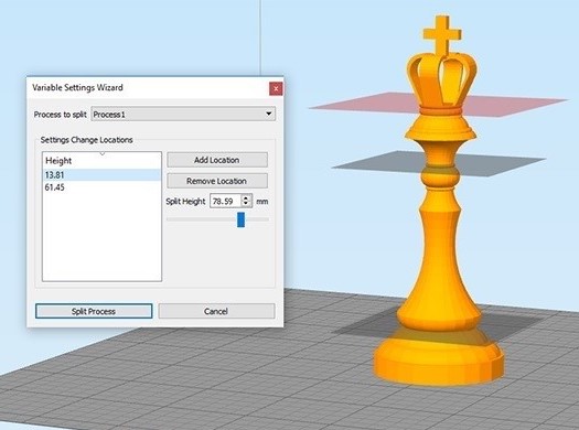
The Variable Settings wizard makes it easy to define the different settigns that you want for each region of your model. To open this wizard, go to Tools > Variable Settings Wizard. At the top of the wizard, you will be able to select the original process that you want to use as a template. The remainder of the wizard is dedicated towards helping you select and visualize the different locations where you want to initiate a settings change. For example, if our Chess Piece model is 100mm tall, but we wanted to use different settings for the top and bottom halves of the model, we would use this wizard to add a single location at 50mm where the settings would begin to change.
Follow the steps below to add all of the locations where you want to change the settings for your model.
- When using the wizard, you will see a transparent red plane cutting through your 3D models in the Simplify3D workspace. Use the horizontal slider to move this plane onto the location where you want to change the settings for the print. If you already know the exact Z-axis location, you can also enter this number manually in the “Split Height” input box.
- After you have positioned the red plane at the correct Z-height, click “Add Location” to add this location to the list.
- Repeat steps 1-2 for each additional location you want to add. You can add as many locations as you want.
- Once you are done, click the “Split Process” button in the lower left to finalize the changes.
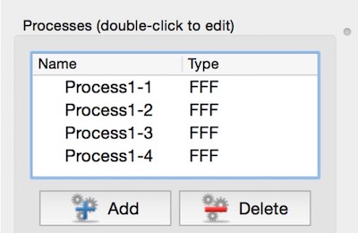
After you exit the wizard, you will notice that the original process has been split into multiple parts. Each part will include the name of the original process as well as a number to denote which region this process controls. For example, we added 3 split locations for our chess piece model. The original process was called “Process1”, so after using the wizard, we are left with “Process1-1”, “Process1-2”, “Process1-3”, and “Process1-4”. “Process1-1” controls the settings at the very bottom of our chess piece, while “Process-4” controls the settings at the very top of the model.
Customizing the Settings For Each Region
 To edit the settings for a specific region, just double-click on the process that is associated with that region. For example, to edit the settings for the base of our chess piece, we would double-click on “Process1-1”. You can then change any settings that you want for that specific region and click OK to save the changes. If you want to edit settings across multiple processes at the same time, you can use another useful feature in Simplify3D called Process Grouping (click here to view a video tutorial on this subject). You can also verify the exact Z-axis range that a process applies to by going to the Advanced tab and checking the “Start/Stop printing at height” settings.
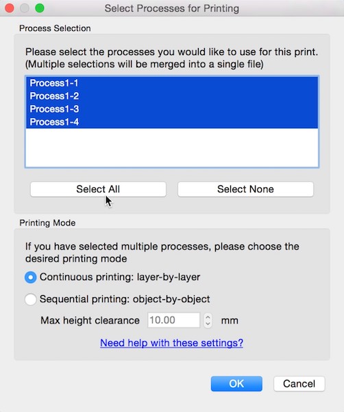 Once you have finished customizing your settings, click “Prepare to Print”. This will open a new window where you can choose the processes that you want to include for this print. In our case, we will choose “Select All” so that we select all 4 of the processes that we just created. Please also make sure to select the “Continuous printing” mode and then choose OK to begin slicing your model. The software will automatically combine the settings for each region of your model into a single print, giving you complete control over the results.
Once slicing has finished, you will be taken to the Preview Mode where you can view a simulation of the print to verify your changes. You can change the preview coloring mode to “Current Process”, which will use a different color for each of the processes that you created. This is a great way to verify which sections of your model are printed by each process. Once you are happy with the changes, you can begin printing your newly customized model!
Optimized Results
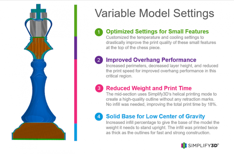
As you can see, printing with multiple processes is an extremely powerful feature! For example, the Chess Piece in the diagram below was printed with varying properties to improve the print quality in different sections and provide a lower center of gravity, all while still improving the overall print time by 22%.
Now that you know how to customize the settings for each region of your model, be sure to check out our complete article library for more advanced tips to help you improve your prints!