Adding and Modifying Support Structures
In this tutorial, we will explain everything you need to know about support structures. These thin, break-away structures are used to support steep overhangs and cantilevered sections of your model. The Support Generation Tool makes it easy to add, move, or delete supports. The supports appear as individual pillars in the software, but are constructed as a network of interconnected pieces for easy removal from your model.
When to Use Supports
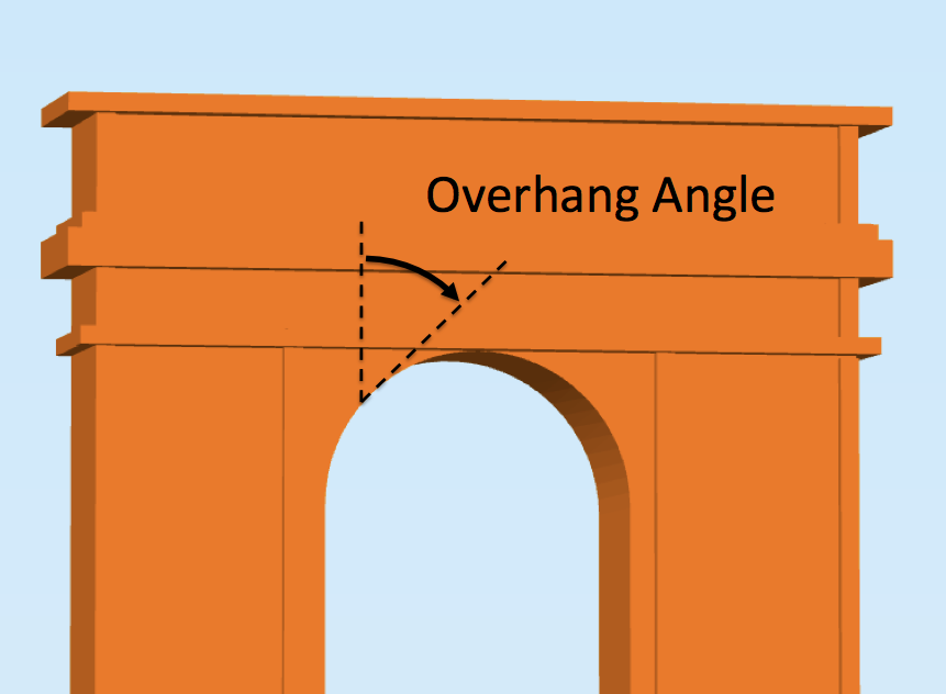 When do you need supports? Supports are used when models have steep overhangs or unsupported areas. For example, if you printed an arch, the very center of this arch might require support material because when your printer tries to print that top layer, there would be nothing else supporting it from below. If you tried to print this arch without support material, you might notice that the top layers of the arch seem to sag and droop because there is nothing to support the molten plastic as it is extruded out of the nozzle.
A general rule of thumb is that most extrusion-based printers can support overhang angles less than 45 degrees. At these shallow angles, the majority of the plastic layer is supported by the previous layer below it. If you go to steeper overhang angles, you might start to notice the edges of your layer begin to deform, and that is when you might want to consider adding support material to the part.
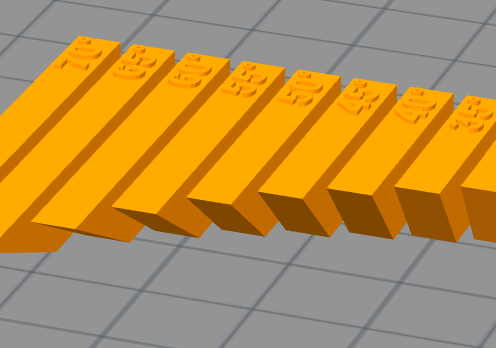 To begin, let’s look at a common model that can help identify what types of overhang angles your printer can support. The Massive Overhang Test by thingster can help identify what types of angles your printer can smoothly produce. If you try to print this part on your machine, you will probably notice that the 60-70 degree sections will not be as smooth as you would like. The performance of these overhangs will depend on your layer height, temperature, material, and several other factors, but this test part will help establish a useful baseline of what types of angles your machine can support. As an example, let’s assume that your massive overhang test print shows that any angle greater than 45 degrees would start to require support material. We will use this information in the next part of the tutorial.
How to Add Supports
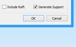 When you encounter a model that will require support material, Simplify3D makes it easy to add them to your print. Let’s start by importing a model that we know will require support. We will be using alien000′s Moai statue. Note that this model is fairly large, so you probably want to scale it down to about 25% of its original size after you import it into the software (if you need help with this step, please read our Importing and Manipulating Models tutorial). When looking at this model, it is clear that there are several areas that will probably violate our 45 degree overhang angle limit. Add a new FFF process, or edit an existing one, in order to print the Moai model. To add support material for this model, open the settings for your FFF process and enable the Generate Support Material option. If you click Prepare to Print!, you will notice that the software has already added the necessary support structures for the nose, chin, eyebrows, and ears.
How to Modify Where Support Material is Placed
While the software makes this process extremely easy, it also offers additional options if you want more control over where the support material is placed. For example, what if you didn’t want to print support material inside the Moai statue’s nose? Maybe you have printed this model before and the nose printed well without the support material. If you could remove the support material from this location, it would give you less to clean up at the end of the print. To do this, first we need to return to the model view. If you were previously looking at a line-by-line G-Code preview, be sure to exit the preview so that you are looking at the raw digital model of the Moai statue. To open the support generation toolbar, go to Tools > Customize Support Structures, or click the very last icon in the toolbar on the right side of the screen.
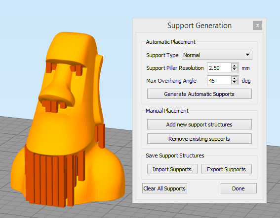 The support generation toolbar consists of several sections. The top section contains all of the automatic support generation options that allow the software to give you a recommendation about where it thinks support material is needed. This can save a lot of time by giving you a starting point for any later modifications. You can also change the Support Type from Normal to From Build Platform Only, which will only generate supports that are touching the build plate, which can be useful if the supports generated will be trapped within the part or otherwise difficult to remove. Once you select an option, press the Generate Automatic Supports button. This will produce a preview of the recommended support structures based on the overhang angle that you specify. This preview shows a series of vertical pillars that represent where support structures would be needed. Note that the pillar shape is simply a preview. The actual print will still use the same back-and-forth webbing pattern that you saw earlier in the G-Code preview. The only other option in this section is the support pillar resolution, which determines the size of each individual support pillar. If you have a very complex model with lots of tiny features, you might want to use a smaller value like 1-2mm. In this case, the features are all large and pronounced, so a resolution between 4-6mm should be fine. A larger resolution also makes the pillars easier to interact with.
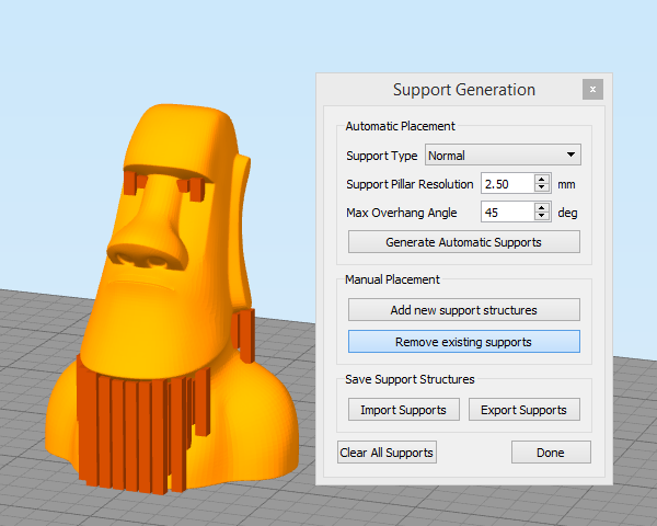 The next section in the support generation toolbar includes a few options that will help us manually add or delete existing support material locations. We can combine these tools to get the perfect support material layout for our model. We mentioned earlier that we might want to remove the support material under the Moai statue’s nose. To do this, simply press the “Remove existing supports” button and then left-click the support pillars on the screen that you wish to delete. When you are done removing these pillars, click the “Remove existing supports” button again to exit that mode. If you want to add support material in new areas of the model, the process is very similar. In this case, you would click the “Add new support structures” button and then click on the locations where you would like the new support pillars to be placed. As before, click the button a second time when you are finished to exit that editing mode.
Saving Your Factory File
After you have made several changes to your model’s support structures, you may want to save your work so that you reload it later on. The best way to do this is to simply save a “factory file” for your current workspace. The factory file will contain your imported STL file, the support structures you have created, any FFF processes you have defined, and even the orientation and positioning of the models on your build table surface. It is a great way to save all of your work so that you can pick up right where you left off or to share your file with a friend who has a similar machine. To save a factory file, go to File > Save Factory File As. You also have the option to save the support structures by themselves from within the support generation toolbar, but this is typically not recommended as it will not include the relative placement of the original STL file.
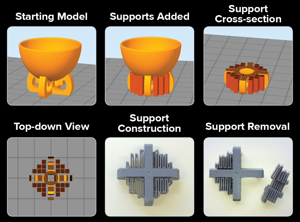 When you view your supports on your monitor, they appear as individual pillars, but when they are constructed, the supports will be constructed to form a network. These support networks are easy to remove from your part! In the image on the left, you can see supports as they are added, previewed, constructed and removed.
Advanced Support Settings
There are additional FFF settings that are available to control how the actual support structures will be printed. To display these options, click Show Advanced in the bottom left of your FFF settings. This will bring up several additional tabs that contain many of the advanced settings that are used to produce your prints.
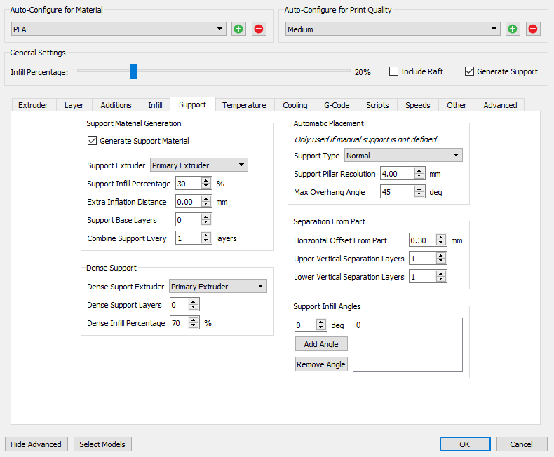 Click on the Support tab to see the various settings that control how your support material is printed. Notice that the Automatic Placement section includes the exact same options that were found in the support generation toolbar. If you do not need to manually edit the support structures for your model, you can simply configure these settings appropriately and let the software automatically generate the support structures without needing to open the Customize Support Structures window like we did previously.
The Separation from Part section includes all of the settings that determine how easily the support material will break away from your final solid part. The horizontal offset will determine how much spacing there is between the support structures and the outline of your part. If you are having trouble removing your support material, you may want to increase this setting so that there is a larger gap between the support and the part. A value between 0.2-0.4mm is usually sufficient. Once you have entered the desired values, click Save so that the next model preparation will use the updated settings.
Congratulations! You have now covered everything you need to know about adding and modifying support structures in the Simplify3D Software! The ability to modify where these break-away structures are placed can make a big impact in the quality of your prints and can save you a lot of post-processing time.