Simplify3D and the MakerGear M2
 This page will help you get up and running with your new MakerGear 3D printer using the All-In-One 3D printing software by Simplify3D. The M2 is one of MakerGear’s flagship 3D printers and is currently available in both kit and fully assembled versions. If you are trying to assemble the kit form of this printer, please start with MakerGear’s Assembly Instructions. If you have already assembled your printer or you purchased the fully assembled version, you are ready for the remainder of this tutorial.
Final Hardware Checks
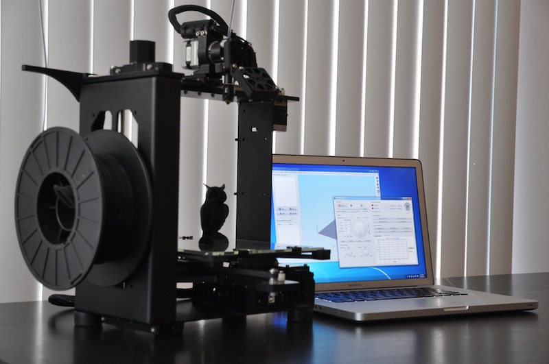
 Before we dive into the software, there are a few final hardware checks you should perform before using your MakerGear M2. If you’re confident your printer is ready to go, you can jump directly to the Software Setup Instructions. The fully assembled version of the M2 comes with several additional pieces you will need to install before performing your first print. These include the filament spool holder (plus 4 black M4 screws), the filament guide arm (plus 2 silver screws), and the clear plastic filament guide tube. The filament spool holder is installed on the left side of the M2 using the 4 included screws as shown in the picture. The spool of PLA or ABS filament can rest on this cylinder so that it is free to rotate during printing.
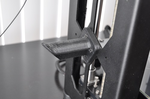
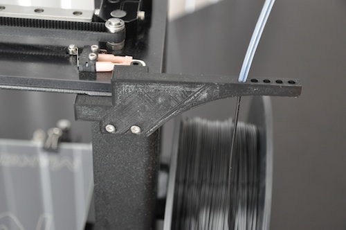 The filament guide arm must also be installed to help direct the plastic filament to the M2’s extruder. The guide arm attached to the backside of the M2 using the 2 silver screws as shown in the photo below. We actually chose to use hockenmaier’s upgraded support arm (available here) since it seemed to match the size of our spool a little better. The original guide arm installs in the same manner. If you forget to install this guide arm, the filament won’t be adequately supported during feeding which can cause the fragile 1.75mm filament to snap during printing.
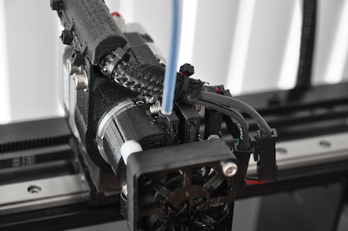 At this point, you can mount your filament spool on the installed holder and route the 1.75mm filament through the tiny hole in the guide arm. Make sure the spool is mounted such that the plastic filament runs straight up vertically through the hole in the guide arm and is not at a sharp angle coming off of the spool. The plastic filament should slide through this hole smoothly, so you may need to use a small drill bit or file if yours is too snug. Now comes the last remaining piece. The clear plastic filament guide tube will help guide your filament from the hole in the filament guide arm into the hot extruder. Run the 1.75mm filament through the guide arm, through the clear plastic tubing, and finally into the small hole in the top of your extruder. The hole may be somewhat hidden beneath the wiring harness, so refer to the picture if you’re having trouble finding it.
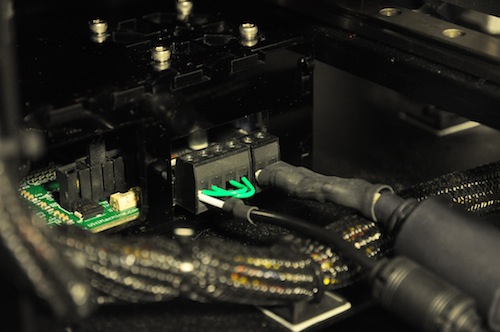 At this point the mechanical assembly of the M2 is complete and you can power it on in preparation for connecting to the Simplify3D software. There are two power supplies included with the M2, a 19V (for the steppers and electronics) and a 12V (for the heated bed, the larger of the two power supplies). The 19V power supply has a 4-pin connector at the end, while the 12V power supply has a 2-pin connector. These connectors plug into the RAMBo electronics board from the backside of your M2. The 2-pin connector will plug in on the side closest to your filament spool and the Z-axis rods, while the 4-pin connector is on the side closest to the X-axis motor. Once your M2 is powered up, the case fans on the electronics enclosure will spin up to about half power. You should be able to hear them spinning confirming that everything has been attached correctly.
Software Setup
The software comes with all of the necessary tools required to operate your M2. It’s a complete integrated package so it’s the only piece of software you’ll need. The software communicates with your printer via the supplied USB cable. If you’re running Linux or OS X, you can move on to the next step. Windows users may need to install the Arduino and RAMBo inf driver files (found here and here).
For Windows users, the steps to install the RAMBo drivers are given below (from MakerGear)
- Power on your M2 by plugging the 6-position black power connector to the rear of the RAMBo board, and plugging in the two power supplies.
- Plug the USB cable’s squarish side into the RAMBo USB port, then the flat side into a USB port on your Windows computer.
- Windows will spin for a bit trying to find and install a driver, then decide that it cannot install it.
- Click Start, then type “Device Manager” and press Enter. This brings up the Windows Device Manager. Alternately this can be accessed in Windows 7 by right-clicking My Computer, Properties; Device Manager is in the list on the left side. In XP, right-click My Computer, Properties; Device Manager is under the Advanced tab.
- In Device Manager, you will be shown a list of all devices connected to your computer, including the logical structure of the computer’s internal components. The section we are interested in is usually “Other Devices.” Under that heading you should have an “Unrecognized Device.” If you do not, check under “Universal Serial Bus controllers.”
- To confirm that your Unrecognized Device is your M2, disconnect the USB cable and watch Device Manager. If the Unrecognized Device disappears, reconnect the USB cable and proceed.
- Right-click the Unrecognized Device and click “Update Driver Software.” Then click “Browse my Computer for driver software,” and on the next page browse to the folder on your computer where you extracted the INF file from the RepRap site (for RAMBo), or the Arduino IDE under e.g. arduino-1.0.1\drivers, and click Next. Windows should then select the correct driver. For the older Arduino device, if Windows asks you which driver to install, select “Arduino Mega 2560 R3.”
- In Device Manager, your Unrecognized Device should have now changed into an “Arduino Mega 2560 R3” or “RAMBo 3D Printer Electronics Board”, with a COM port after it, under the “Ports” heading. Make note of which COM port it is installed as (COM3 is common), we will need that information shortly.
Linux and OS X users already have the required drivers and can simply connect the USB cable from the M2 to their computer.
Connecting to your M2
After opening the software, you will be greeted with the main interface window including a virtual representation of your printer’s build platform. The software is configured to work with Marlin or Sprinter firmwares out of the box, which is what comes preinstalled on all existing M2’s. If you need to change these settings for any reason, they can be found by going to Tools > Firmware Configuration. We will be using this main window more later, but for now, let’s open the Machine Control Panel so we can test that the printer is fully functional.
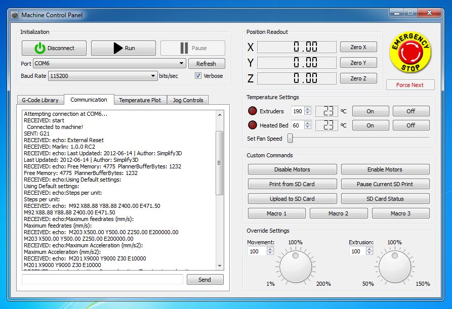 To open the Machine Control Panel, simply press Ctrl-P (or Command-P on the Mac). Alternatively, you can also go to Tools > Machine Control Panel or click the gear icon in the quick access toolbar. To connect to your printer, you will need to choose the correct port, baud rate, and then click the big Connect button. After you connect the USB cable from your printer, you may need to click the Refresh button for the appropriate port to show up. Once you have selected the appropriate port, choose the correct baud rate to match your firmware settings. The Marlin firmware on the M2 uses 115200 bps by default. After the settings are correct, press Connect and the software will try to connect to your printer. If the connection fails, make sure your printer is plugged in and powered on and that the USB cable is connected between the printer and the computer. You may also need to try a different port if more than one is available.
Controlling your M2
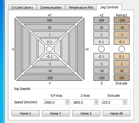 Once you’re connected to your M2, you can use the Machine Control Panel to manually control your machine in preparation for printing. The first thing you might want to check is that your motors are all connected and working properly. You can do this by clicking the Jog Controls tab to bring up the interactive jog panel for making small incremental moves. To manually move your printer, click the button associated with the distance you would like to move on each individual axis. Start with small value like 1 or 10mm and make sure expected movement directions are correct. The default jog speeds should be suitable for the M2, but you can modify those at the bottom of this section as well.
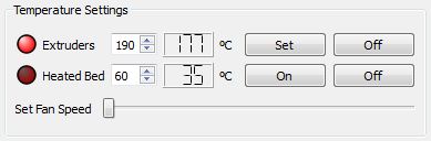 The extruder and heated bed on the M2 can also be controlled using the MCP. The red lights beside extruder and heated bed temperatures indicate when either of these heaters are turned on. Enter the appropriate temperature and press the On button to begin heating. The red circle should light up and you temperature should begin rising.
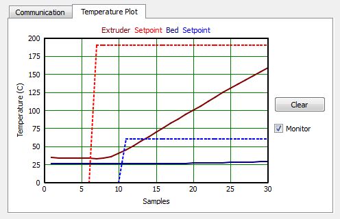 You can use the Temperature Plot tab to see a live view of the current temperatures on your M2. If you want to stop polling temperatures at any time, simply uncheck the monitor button. Before we try extruding from your nozzle, make sure the extruder temperature is heated up and stabilized. 190C is good for PLA and something near 225C is reasonable for ABS. Once the nozzle is heated, go back to the Jog Controls tab and choose the appropriate extrusion distance. 10mm is usually a good starting point. If you are just inserting the filament for the first time, you may need to extrude a larger distance to get the filament to feed all the way through the nozzle. It is typically a good idea to preheat and prime your nozzle following these steps prior to beginning a print.
Starting a Print!
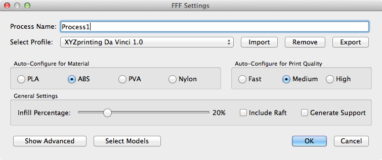 The main interface window is where you will import STL files and prepare the G-Code instructions required for printing. A Quick Start Guide is included with each software installation to help illustrate the process of preparing an individual model for printing. This guide can be accessed by going to Help > Quick Start Guide. As you work through the guide, you will import an STL file, position it on the build table, and add a FFF process that will determine how that model is printed (FFF stands for Fused Filament Fabrication and is the industry term for 3D printing). The settings for each FFF process play a large role in the quality of the final printed object. To make things simpler for our users, the software already includes a profile that has been specifically configured for the M2. You can load this profile by selecting it from the drop down list in the FFF Settings window. At this point, you should be ready to follow the remainder of the Quick Start Guide to begin printing on your new M2.
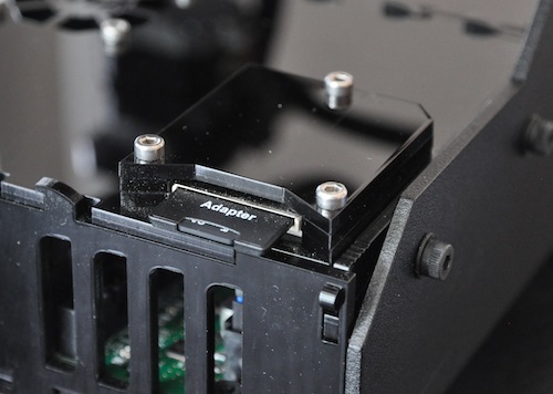 The MakerGear M2 is also equipped with an SD card reader and we would strongly suggest copying your large G-Code files directly to the SD card. Simply unplug the card and insert it into your computer to copy the files. The Marlin firmware requires the use of the 8.3 naming convention, so the filenames on the SD card can only have up to 8 uppercase characters for the filename and up to 3 uppercase characters for the file extension. For example, “3D_Knot_for_M2.gcode” would need to be renamed to something like “M2KNOT.G” when placed on the SD card. Once you have plugged the card back into your M2, you can use the “Print from SD Card” button in the Machine Control Panel to begin the print. This is particularly useful for large parts so that you do not need to have your computer attached and awake for the entire print. It also offers a much lower latency that USB serial protocols which allows for better print quality.
That’s the end of this guide, but if you have any further questions, you can ask them in our User Community or directly on the MakerGear Google Group.
Happy Printing!